Making a float-making lathe.
-
Marc

- Sea Trout
- Posts: 4011
- Joined: Sun Mar 10, 2013 11:14 am
- 11
- Location: Co Durham, land of the prince bishops
Re: Making a float-making lathe.
Lost for words. Both skill and workmanship are, well, amazing.
Marc. (Prince of Durham)
“A life that partakes even a little of friendship, love, irony, humor, parenthood, literature, and music, and the chance to take part in battles for the liberation of others cannot be called 'meaningless'...”
“A life that partakes even a little of friendship, love, irony, humor, parenthood, literature, and music, and the chance to take part in battles for the liberation of others cannot be called 'meaningless'...”
-
MGs

- Pike
- Posts: 6422
- Joined: Wed Nov 02, 2011 2:24 pm
- 12
- Location: Cornwall
Re: Making a float-making lathe.
Simply brilliant. A thing of beauty. As regards drilling stems to fit wire eyes. This does work. I have done it on some bodied floats. It takes a steady hand with my wobbly pillar drill but shouldn't be a problem with your set up. I used superglue to hold the eyes in but a barb would work equally well.
Old car owners never die....they just rust away
-
Kevanf1

- Arctic Char
- Posts: 1563
- Joined: Sat Oct 06, 2012 2:22 pm
- 11
- Location: Cheslyn Hay, Staffordshire
Re: Making a float-making lathe.
Wow! Just wow! Sorry, I need to find some cloth now to mop up the drool 
Currently reading......Go Fishing For Bass and Go Fishing For Skate and Rays both by Graeme Pullen, The Kill Switch by James Rollins, Raspberry Pi Manual - Haynes, 'Make: Electronics by Charles Platt' & the 'Myford series 7 manual by Ian Bradley'
-
Dave Burr

- Honorary Vice President
- Posts: 13511
- Joined: Fri Jul 20, 2012 7:03 pm
- 11
- Location: Not far from the Wye
- Contact:
Re: Making a float-making lathe.
Good grief - pure engineering genius 
-
Barney

- Grayling
- Posts: 733
- Joined: Thu Mar 28, 2013 12:09 pm
- 11
- Location: Woolwich, S/E London
Re: Making a float-making lathe.
-
Hovis

- Tench
- Posts: 2527
- Joined: Tue Apr 02, 2013 1:54 pm
- 11
- Location: Nottingham
Re: Making a float-making lathe.
Utterly amazing can you imagine what the floats will be like?
I have laid aside business, and gone a'fishing.
Izaak Walton
Izaak Walton
-
Julian

- Salmon
- Posts: 7463
- Joined: Sun Jan 15, 2012 3:42 pm
- 12
- Location: North Buckinghamshire
Re: Making a float-making lathe.
Truly amazing craftsmanship 

There is no peace on earth like the peace of fishing in the early mornings
-
Watermole+

- Chub
- Posts: 1056
- Joined: Thu Mar 15, 2012 11:07 pm
- 12
- Location: Devon & Cornwall border
Re: Making a float-making lathe.
Part 15. Project finished and Tested!
..At the end of the last part, we were making the 'Steady'. This has now been completed and the next stage was to make the means of holding various sixes of balsa or other materials securely, without crushing or deforming it and to prevent it from slipping or spinning in the chuck.
This was a bit of a puzzle initially but was solved quite easily in the end. I had the idea from looking at an old carving dish which had small spikes to prevent the joint from moving.
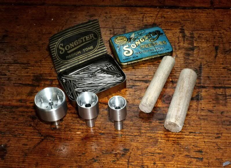
The result was to turn up some little, lightweight holding jigs from aluminium and insert some gramophone needles inside!!
So far, I have only made three for the size samples in stock, but it will be straightforward enough to make a similar holder for any size material, if necessary.
Here are the ones already made, some balsa pieces and the tin of old gramophone needles I mentioned in an earlier post.
Now we are ready to go!
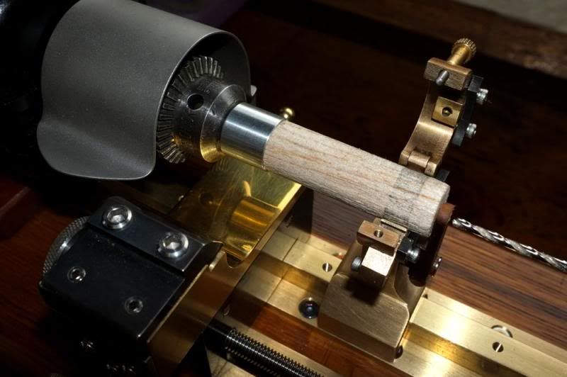
Here you see one of the holders mounted in the chuck, the balsa blank pushed into place and held centrally by the finished Steady (which is shown in the open position for material loading/unloading). This attachment has reversible jaws (made from the pins of a 3-pin plug) which are set so as to just contact the balsa without causing undue friction. The little movable Tufnol lever in front is adjusted to prevent the balsa dragging out of the holder when the drill is withdrawn for swarf clearance.
Now we are drilling the hole, using the rapid drilling slide..
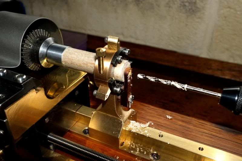
..which has produced a nice, clean hole of good size and we are ready for the next ops..
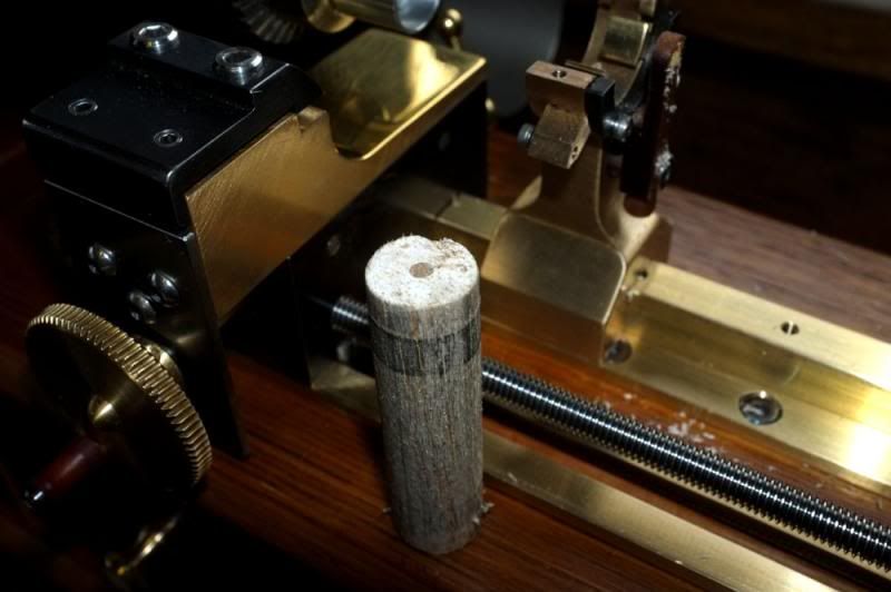
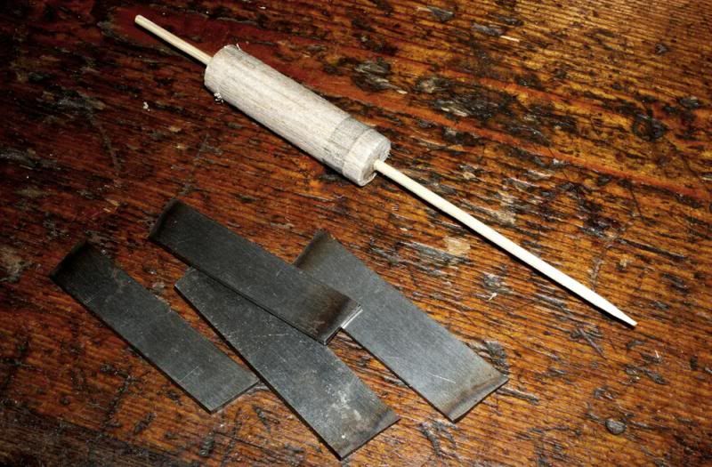
The drilled balsa blank was then glued on to a 3mm wooden skewer and set aside to dry. This is not meant to be any particular specialist float, merely a test piece of a general 'Avon' design. The body length is about 1 3/4" and the skewer about 5 1/2" long.
The next step is to make a cutting blade which will produce the form. I have had a few doubts previously, as to whether this will be possible to do, but initial tests have been favourable so I think that we should get a result of some kind! If this works, it means that literally, any number of identical float bodies can be easily produced.
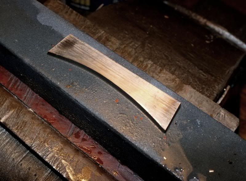
I have cut up some pieces of gauge plate and roughly ground them to the 'blank' shape..
Next, we roughly made the profile shape by hand, using a mounted grindstone in a power drill. The tapered stone will produce the 'relief' for the blade edge.
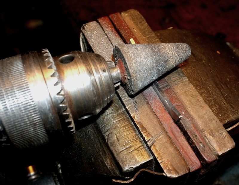
This is the approximate shape..
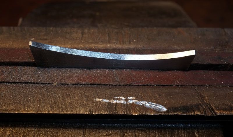
..but it now requires careful finishing, hardening & tempering, then hand honing on an oilstone to give a fine, razor sharp cutting edge, as follows...
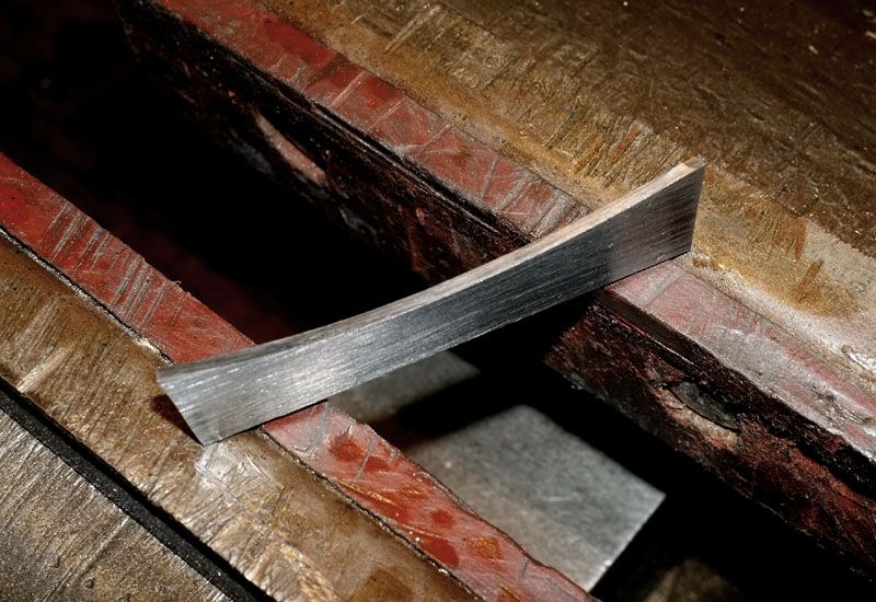
Now, owing to a classic boob on my part, I have not made the blade wide enough to reach the job!!
It would be simple enough to make another blade but it would be better to make a blade HOLDER which will allow us to use very narrow blades to make those classic, very fine bodies..
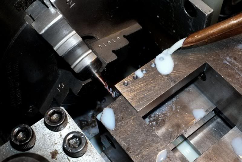
Next step then, is to make a holder. In a nutshell then, a small block of gauge plate steel was shaped up to 3/4" x 1/2" and about 2" long. We drilled & tapped M3 holes along one side..
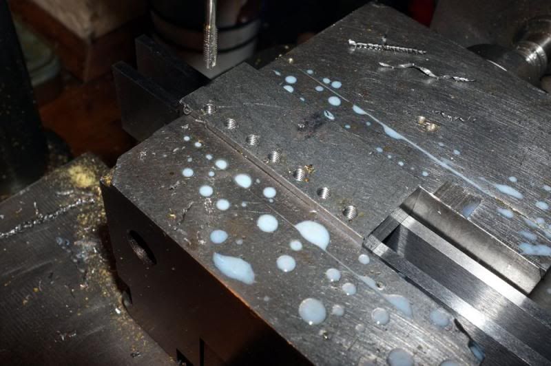
..then cut a 1/8" slot along it, 1/4" deep..
Using hacksaw and files, it was then finished to shape, hardened & tempered to produce this.
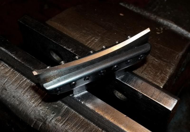
The blade is held in place by grub screws on BOTH sides, which will give some vertical adjustment. The tab which locates in the tool holder, is dovetailed so that it will lock securely in place without moving.
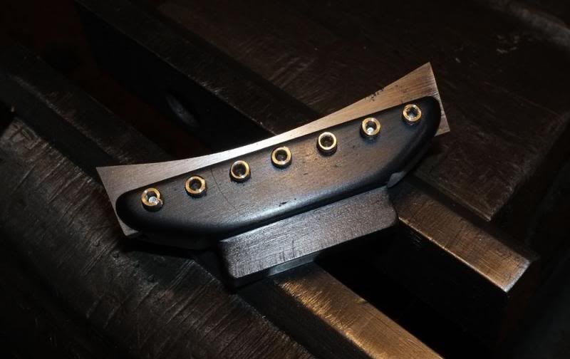
The grub screws are a little proud but they can be trimmed down to length later.
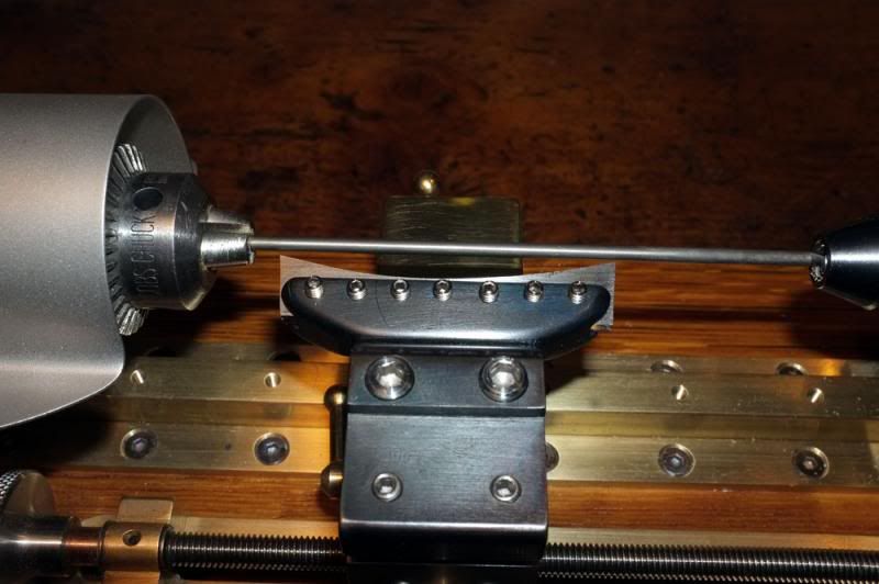
Next, the blade was set up and positioned parallel by using the welding rod between chuck and tailstock as a guide.
It would be impossible to cut the body profile, without having some means of supporting the other end of the wooden skewer. We could use the Steady, but I thought a better way would be to make some Delrin supports of different sizes, to fit in the tailstock. It will be a relatively simple matter to make these to suit any size of float stem.
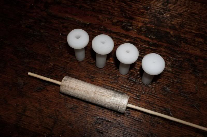
By removing just the one guide screw, the rapid drilling slide was removed from the tailstock and a push-fit delrin insert fitted.
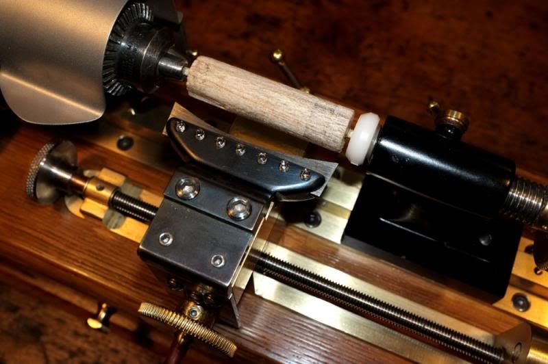
We are now ready to rock 'n' roll!!
Here we go then...
..I have just developed a little problem on the computer so will have to finish this as a separate post later on..
Sorry!
wm+
..At the end of the last part, we were making the 'Steady'. This has now been completed and the next stage was to make the means of holding various sixes of balsa or other materials securely, without crushing or deforming it and to prevent it from slipping or spinning in the chuck.
This was a bit of a puzzle initially but was solved quite easily in the end. I had the idea from looking at an old carving dish which had small spikes to prevent the joint from moving.
The result was to turn up some little, lightweight holding jigs from aluminium and insert some gramophone needles inside!!
So far, I have only made three for the size samples in stock, but it will be straightforward enough to make a similar holder for any size material, if necessary.
Here are the ones already made, some balsa pieces and the tin of old gramophone needles I mentioned in an earlier post.
Now we are ready to go!
Here you see one of the holders mounted in the chuck, the balsa blank pushed into place and held centrally by the finished Steady (which is shown in the open position for material loading/unloading). This attachment has reversible jaws (made from the pins of a 3-pin plug) which are set so as to just contact the balsa without causing undue friction. The little movable Tufnol lever in front is adjusted to prevent the balsa dragging out of the holder when the drill is withdrawn for swarf clearance.
Now we are drilling the hole, using the rapid drilling slide..
..which has produced a nice, clean hole of good size and we are ready for the next ops..
The drilled balsa blank was then glued on to a 3mm wooden skewer and set aside to dry. This is not meant to be any particular specialist float, merely a test piece of a general 'Avon' design. The body length is about 1 3/4" and the skewer about 5 1/2" long.
The next step is to make a cutting blade which will produce the form. I have had a few doubts previously, as to whether this will be possible to do, but initial tests have been favourable so I think that we should get a result of some kind! If this works, it means that literally, any number of identical float bodies can be easily produced.
I have cut up some pieces of gauge plate and roughly ground them to the 'blank' shape..
Next, we roughly made the profile shape by hand, using a mounted grindstone in a power drill. The tapered stone will produce the 'relief' for the blade edge.
This is the approximate shape..
..but it now requires careful finishing, hardening & tempering, then hand honing on an oilstone to give a fine, razor sharp cutting edge, as follows...
Now, owing to a classic boob on my part, I have not made the blade wide enough to reach the job!!
It would be simple enough to make another blade but it would be better to make a blade HOLDER
Next step then, is to make a holder. In a nutshell then, a small block of gauge plate steel was shaped up to 3/4" x 1/2" and about 2" long. We drilled & tapped M3 holes along one side..
..then cut a 1/8" slot along it, 1/4" deep..
Using hacksaw and files, it was then finished to shape, hardened & tempered to produce this.
The blade is held in place by grub screws on BOTH sides, which will give some vertical adjustment. The tab which locates in the tool holder, is dovetailed so that it will lock securely in place without moving.
The grub screws are a little proud but they can be trimmed down to length later.
Next, the blade was set up and positioned parallel by using the welding rod between chuck and tailstock as a guide.
It would be impossible to cut the body profile, without having some means of supporting the other end of the wooden skewer. We could use the Steady, but I thought a better way would be to make some Delrin supports of different sizes, to fit in the tailstock. It will be a relatively simple matter to make these to suit any size of float stem.
By removing just the one guide screw, the rapid drilling slide was removed from the tailstock and a push-fit delrin insert fitted.
We are now ready to rock 'n' roll!!
Here we go then...
..I have just developed a little problem on the computer so will have to finish this as a separate post later on..
Sorry!
wm+
"Are not two sparrows sold for a farthing? Yet one of them shall not fall without your Father knoweth" ..Jesus of Nazareth, King James AV
-
Robbi

- Tench
- Posts: 2926
- Joined: Thu Feb 14, 2013 9:40 pm
- 11
-
Loop Erimder

- Wild Carp
- Posts: 9984
- Joined: Wed Apr 04, 2012 11:33 pm
- 12
- Location: Leicestershire
Re: Making a float-making lathe.
Nooooooooooooooooooooooooooooooooo!!!!!
Brilliant cant wait for the end result
Brilliant cant wait for the end result
Chance is always powerful. Let your hook be always cast; in the pool where you least expect it, there will be a fish