Re: Making the TFF Aerial
Posted: Sun Sep 09, 2012 11:09 pm
Part 10. Making the tension adjuster... ..but it's slooow going..
Do you ever get to a stage with something and then wonder, why am I doing this?
Well, it's been very much like that this week. Spare time has been at a bit of a premium and trying to concentrate on something for the odd half-hour, late in the evening after a long day, is not the best time to try and be creative.
The TFF reel has now got to the stage where a definite decision has to be made about the type of pawl/check spring to have, how to make it adjustable and where best to site it. One of the best-and simplest-ideas is that on the W.R. Speedia reels; a 3-position thumbwheel giving different spring tension on the check pawl.-Just brilliant! The problem with the TFF is entirely of my own making so can't blame anyone else; I wanted a wooden back and by trying to be clever and minimising inside clearance between the drum inner and the backplate, I've managed to box myself into a corner. The line drum is already made so can't, or don't particularly want to alter that-and so just don't have the space to incorporate a Speedia-type wheel. In a way I'm not sorry because this is supposed to be an original sort of design and I don't want to directly copy an existing reel.
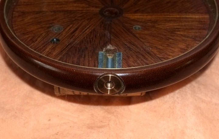
Anyway, after much time-wasting and playing around, I decided that the check adjuster will be set centrally on the rim, just in front of the reel seat and be based on the Hardy fly reel type; viz. A thumbwheel operated internal screw. I know it sounds a bit too unnecessarily complicated, but at a pinch, it will be possible to squeeze it in-and, it will look rather neat externally.
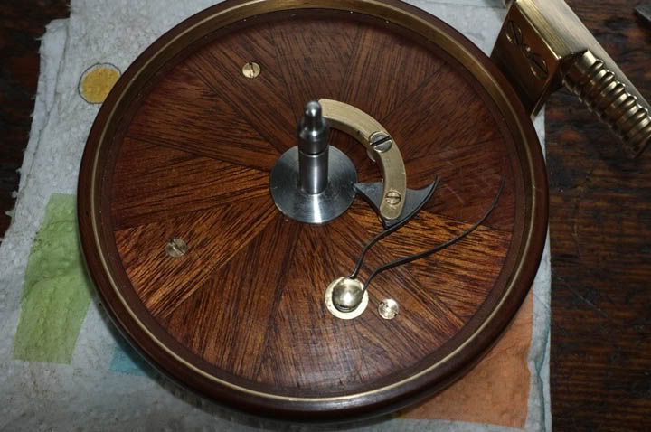
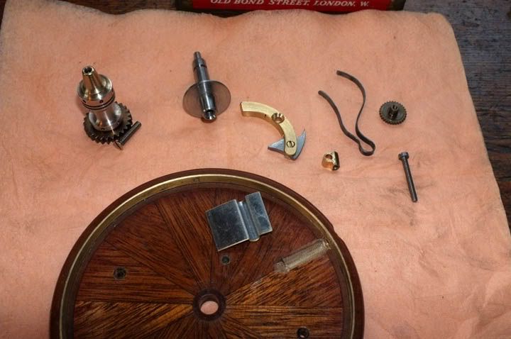
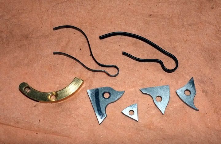
The first thing was to determine the pawl and spring layout. None of these parts are finished yet; in fact, some have since been scrapped, as you will see..
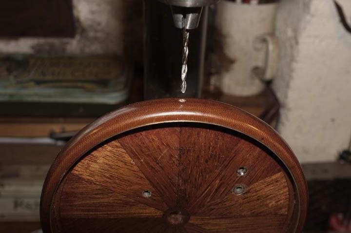
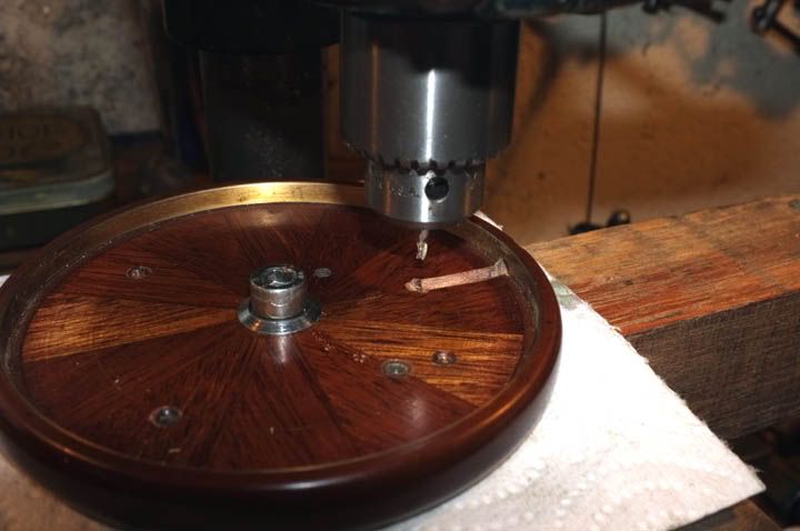
Now we come to the point of no return and drill through the rim. Fortune favours the Brave, so they say, so here we go...
..And straightaway we hit a snag! Having drilled the pilot hole, I found that the bench drill chuck it too small for the long cutter. Nothing for it but to set it up in the lathe and do it that way. I used the 4-jaw for this, holding it very carefully and keeping the speed right down, put the long cutter through. This is to create the groove for the adjuster screw.
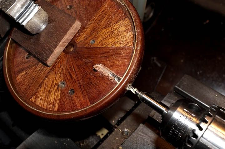
Because of the low speed, it tended to tear the wood a little bit, so will have to sand that out later. Now we have to bore out the hole true and counterbore a recess to accept the tiny bronze bush for the thumbwheel.
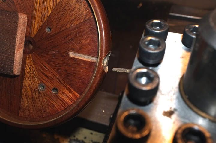
Next, it was back on the bench drill to 'mill' out the little cross-groove for the screw head. (All will become clear soon)
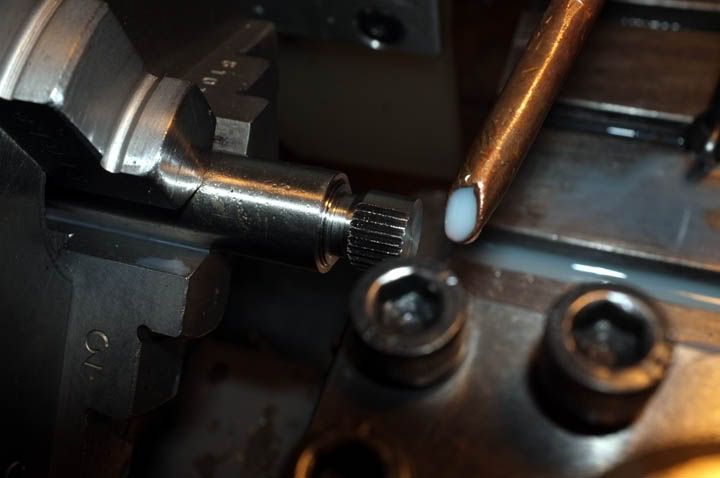
To make the thumbwheel, I turned a piece of harden-able stainless steel and cut the grooves by broaching.
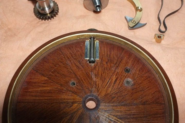
Now, the groove has to be lined to take the little spring holding block which will move up-and down (bear with me on this). I fashioned this from some thin, sheet brass, bending it around a drill shank of the right size and then flattening the sides. You can see the rough shape in this picture. I haven't cut it to length yet.
Now it has been cut, the edges filed to thickness and the ends profiled. Here is a trial fitting.
Although not finished, you can see now how it is (hopefully) going to work. This is an end view of the thumbwheel bearing. (It's actually the second one; I made the first one wrong!) It's an interference fit and has been already pressed in permanently.
Next, I made the block which holds the spring and travels up-and down, when the thumbwheel is turned. I soldered a piece of tube to a pin from a 13amp. plug.
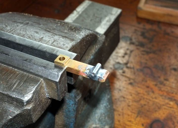
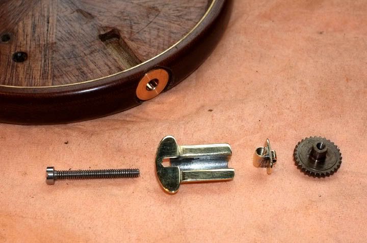
Then hand-filed it to shape, tapped the hole to 8 BA and drilled a 1mm cross hole for the spring wire. I soldered a little piece of brass to the end of the groove lining, to be a 'stop' for the screw-which was made from an 8 BA bolt. The component 3rd from left is what remains of the 13-amp plug pin and tube!
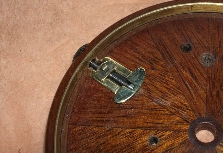
There are some 1.4mm holes to go in yet, which will hold the assembly in place, but here in this trial fitting, you can now see how it works.
Last picture for today shows the bits which are NBG and going in the bin!!
We've nearly got this cracked and can then start on the lever operated check.
More next time.
Regards from wm+
Do you ever get to a stage with something and then wonder, why am I doing this?
Well, it's been very much like that this week. Spare time has been at a bit of a premium and trying to concentrate on something for the odd half-hour, late in the evening after a long day, is not the best time to try and be creative.
The TFF reel has now got to the stage where a definite decision has to be made about the type of pawl/check spring to have, how to make it adjustable and where best to site it. One of the best-and simplest-ideas is that on the W.R. Speedia reels; a 3-position thumbwheel giving different spring tension on the check pawl.-Just brilliant! The problem with the TFF is entirely of my own making so can't blame anyone else; I wanted a wooden back and by trying to be clever and minimising inside clearance between the drum inner and the backplate, I've managed to box myself into a corner. The line drum is already made so can't, or don't particularly want to alter that-and so just don't have the space to incorporate a Speedia-type wheel. In a way I'm not sorry because this is supposed to be an original sort of design and I don't want to directly copy an existing reel.
Anyway, after much time-wasting and playing around, I decided that the check adjuster will be set centrally on the rim, just in front of the reel seat and be based on the Hardy fly reel type; viz. A thumbwheel operated internal screw. I know it sounds a bit too unnecessarily complicated, but at a pinch, it will be possible to squeeze it in-and, it will look rather neat externally.
The first thing was to determine the pawl and spring layout. None of these parts are finished yet; in fact, some have since been scrapped, as you will see..
Now we come to the point of no return and drill through the rim. Fortune favours the Brave, so they say, so here we go...
..And straightaway we hit a snag! Having drilled the pilot hole, I found that the bench drill chuck it too small for the long cutter. Nothing for it but to set it up in the lathe and do it that way. I used the 4-jaw for this, holding it very carefully and keeping the speed right down, put the long cutter through. This is to create the groove for the adjuster screw.
Because of the low speed, it tended to tear the wood a little bit, so will have to sand that out later. Now we have to bore out the hole true and counterbore a recess to accept the tiny bronze bush for the thumbwheel.
Next, it was back on the bench drill to 'mill' out the little cross-groove for the screw head. (All will become clear soon)
To make the thumbwheel, I turned a piece of harden-able stainless steel and cut the grooves by broaching.
Now, the groove has to be lined to take the little spring holding block which will move up-and down (bear with me on this). I fashioned this from some thin, sheet brass, bending it around a drill shank of the right size and then flattening the sides. You can see the rough shape in this picture. I haven't cut it to length yet.
Now it has been cut, the edges filed to thickness and the ends profiled. Here is a trial fitting.
Although not finished, you can see now how it is (hopefully) going to work. This is an end view of the thumbwheel bearing. (It's actually the second one; I made the first one wrong!) It's an interference fit and has been already pressed in permanently.
Next, I made the block which holds the spring and travels up-and down, when the thumbwheel is turned. I soldered a piece of tube to a pin from a 13amp. plug.
Then hand-filed it to shape, tapped the hole to 8 BA and drilled a 1mm cross hole for the spring wire. I soldered a little piece of brass to the end of the groove lining, to be a 'stop' for the screw-which was made from an 8 BA bolt. The component 3rd from left is what remains of the 13-amp plug pin and tube!
There are some 1.4mm holes to go in yet, which will hold the assembly in place, but here in this trial fitting, you can now see how it works.
Last picture for today shows the bits which are NBG and going in the bin!!
We've nearly got this cracked and can then start on the lever operated check.
More next time.
Regards from wm+