Making a float-making lathe.
-
GarryProcter

- Arctic Char
- Posts: 1898
- Joined: Sun Apr 29, 2012 12:48 pm
- 12
- Location: Wilt Shire
Re: Making a float-making lathe.
Wonderful work, as ever, wm+ One day I'll own a small lathe for floats - so far my hints to Mrs GP about birthday presents have fallen on deaf ears  - but whatever I end up with won't be a patch on your wonderful creation!
-
Watermole+

- Chub
- Posts: 1058
- Joined: Thu Mar 15, 2012 11:07 pm
- 12
- Location: Devon & Cornwall border
Re: Making a float-making lathe.
Part 13. Assembly & setting up.
At last..the build begins!
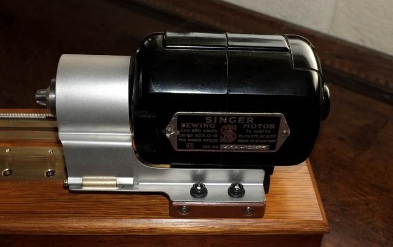
The big mistake I made last time was to fit the motor first and then try to get the brass guide rail all square and in line with it, which proved most difficult. This time, we did it correctly; fix the guide rails down parallel & flat, then set the motor up to suit.
It wasn't easy to get right, but the result was worth it, as you will see.
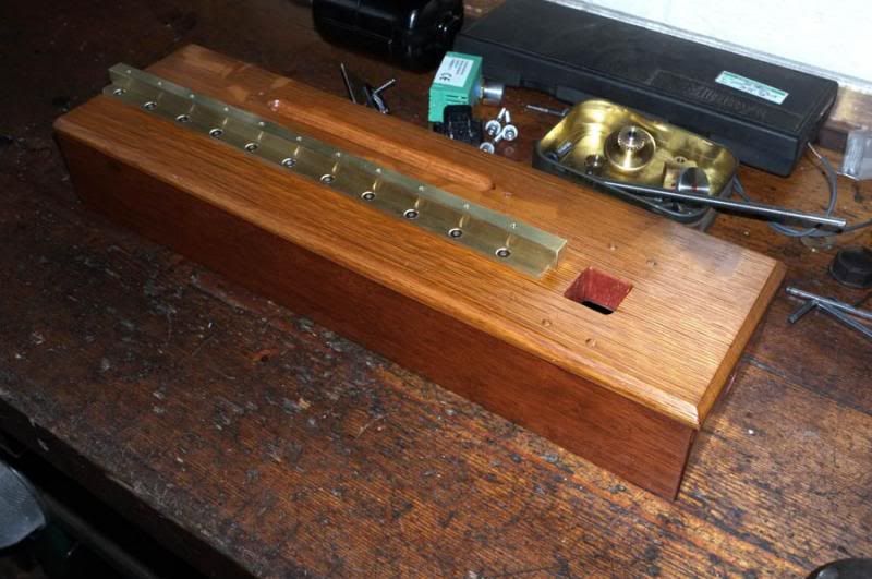
Firstly then, the centre rail was screwed down evenly on to the finished base unit with the side pieces alongside in a similar manner..
The motor was then set up by putting a carbide TiG welding electrode (only used because it is the straightest piece of bar I have) in the chuck, checking firstly that it runs true and then loosely fitting the four, M4 motor fixing bolts from underneath. Next, we ascertained the exact centre height from the bed rail (minus half of the electrode diameter) and added little shims of packing under the motor footings until the height was perfect end-to-end along the bed. The four bolts needed a lot of doing-up and undoing again to get it right both ends as you can imagine, but we eventually got there..
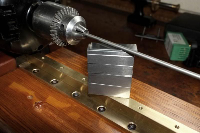
The height was determined by building up gauge blocks underneath. A set of these can be bought quite cheaply now; they might be a little too worn for proper engineering shops, but are still good enough for the work I do. Having now got the height right, it was necessary to get it correct on the 'X' axis, to prevent tailstock misalignment and thus, broken drills. I did this by slackening off the bolts a little, then 'tweaking' the motor position a little at a time, checking with a try-square and gauge block, until it was within an acceptable limit. I got it within 0.006" total, which means the off-set was just 0.003".
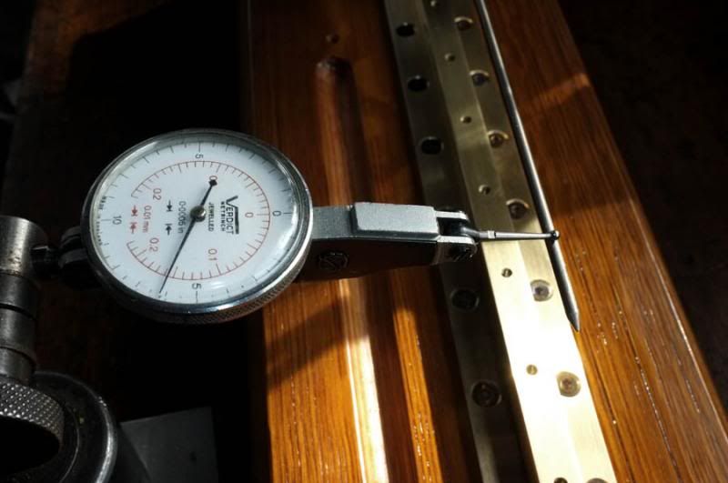
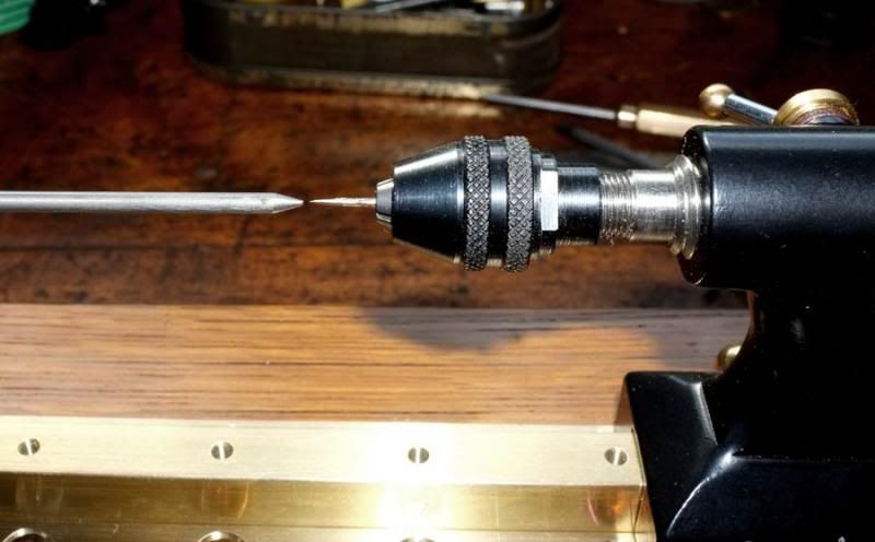
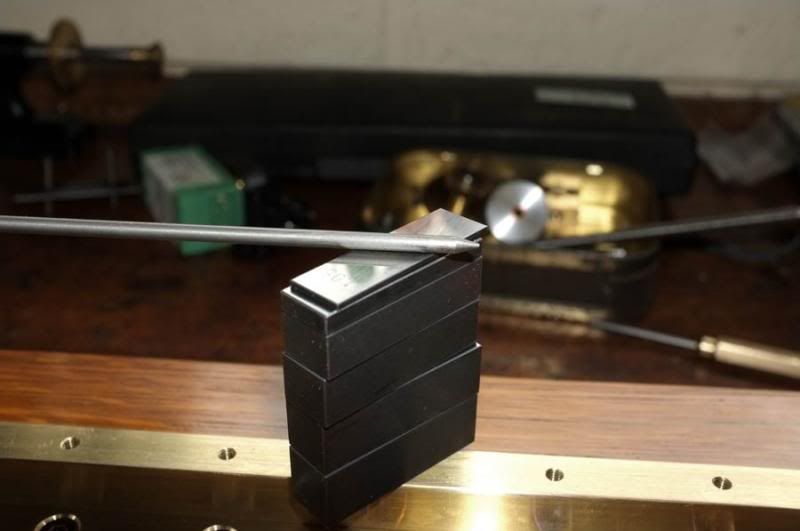
The last picture shows that with a needle in the tailstock chuck, the misalignment is only very small.
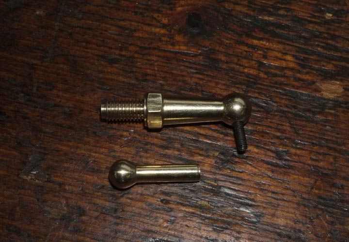
The next step was to fit the cross-slide assembly, which made me realize that I hadn't made the little locking levers for this yet!
I made these in similar fashion as with the tailstock; i.e. making two parts and screwing together, only they came out a bit neater this time (experience teaches..). The steel screw, which joins the two parts is a cut-down 8BA bolt, put in slightly offset. I made two of each of these parts.
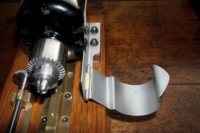
Initial bench testing showed that I ought to make a little chuck guard to prevent getting an eye-full of high-speed particles of debris/oil etc. This was done by firstly fashioning one from pieces of cardboard and then cutting it out from fairly light-gauge stainless steel plate. This was admittedly, a little time-consuming, but an enjoyable exercise in cutting/folding/drilling metal.
The hinge was made by turning an odd scrap piece of brass and drilling it through 1/16" diameter. This was silver-soldered into place and the other part bent to suit. I achieved the radius bend around the chuck by wrapping around a piece of plastic bar!
Here are the two parts of the guard..
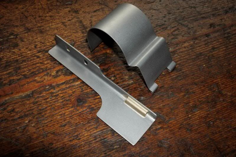
The hinge pin was made from 1/16" silver steel with a brass bead tapped on to one end. I left it a little overlength to enable easy removal.
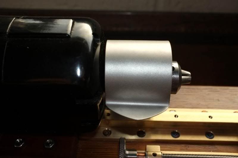
This is the finished guard in position, in open-and closed positions..
Tooling up!
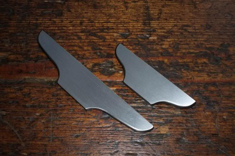
The lathe as such, is now more-or-less complete as a working unit, but will need some tools and equipment before we can start to use it. I thought that, until the cutting tools are made, we could at least try it out by using a conventional tool rest. I ended up making two different sized ones, hacksawing them roughly out of 3/32" thick, gauge-plate steel, then shaping up with files..
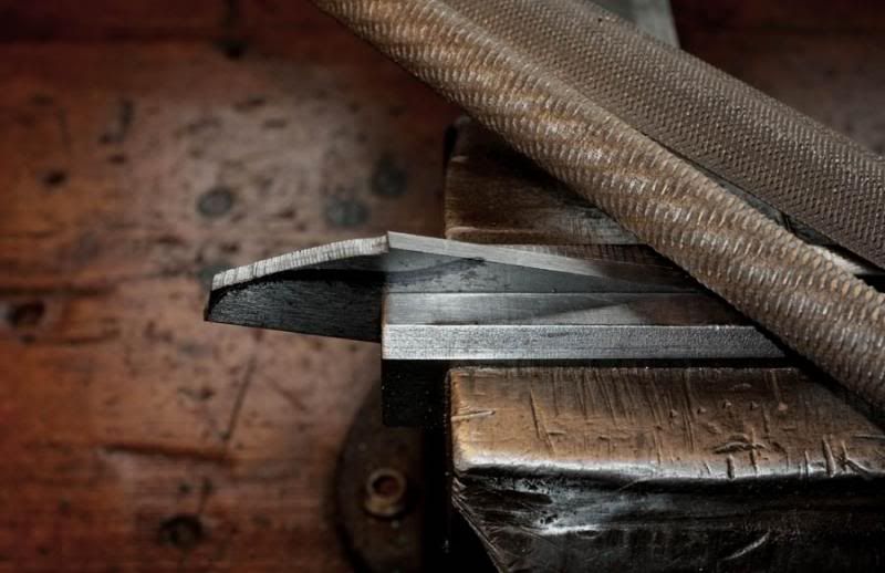
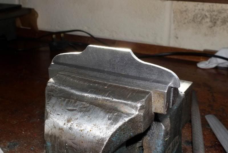
I filed a relief angle of about 10 degrees on the underside..
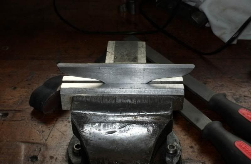
..and radiused off the outside edges to take off the sharpness..
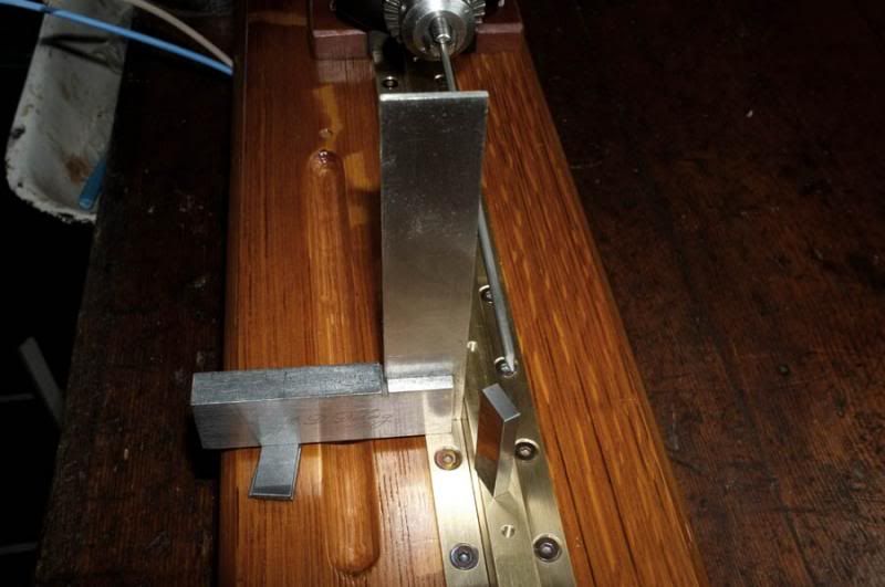
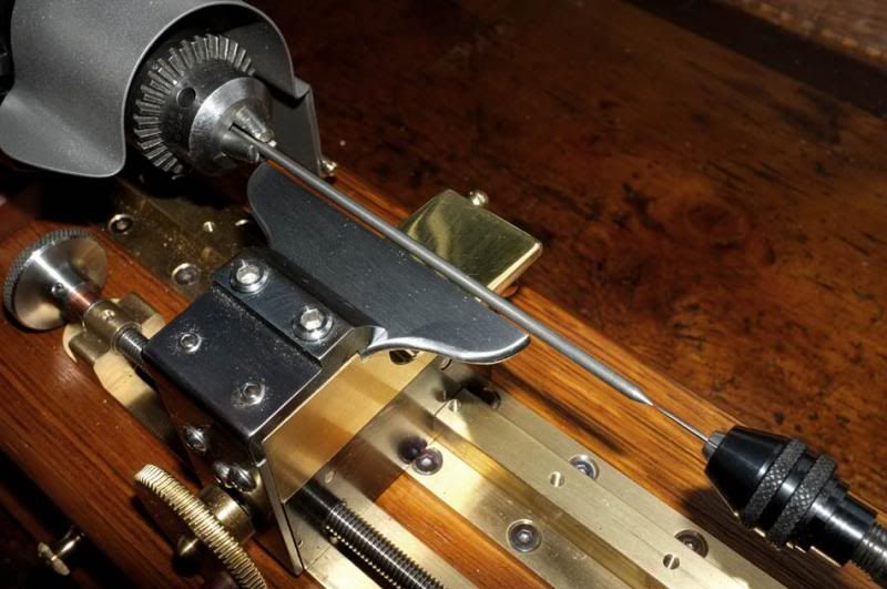
This is the shorter one of the two, shown locked up in position and ready to use. I used the carbide bar again to set the rest and you can see that the misalignment of the tailstock is virtually nothing. 'X' axis travel will allow floats of up to 1 1/4" diameter to be made.
..Next time, I hope to have some tooling made and we will be doing some practical operational testing, starting by tailstock drilling with very fine drills..
Regards to all
wm+
At last..the build begins!
The big mistake I made last time was to fit the motor first and then try to get the brass guide rail all square and in line with it, which proved most difficult. This time, we did it correctly; fix the guide rails down parallel & flat, then set the motor up to suit.
It wasn't easy to get right, but the result was worth it, as you will see.
Firstly then, the centre rail was screwed down evenly on to the finished base unit with the side pieces alongside in a similar manner..
The motor was then set up by putting a carbide TiG welding electrode (only used because it is the straightest piece of bar I have) in the chuck, checking firstly that it runs true and then loosely fitting the four, M4 motor fixing bolts from underneath. Next, we ascertained the exact centre height from the bed rail (minus half of the electrode diameter) and added little shims of packing under the motor footings until the height was perfect end-to-end along the bed. The four bolts needed a lot of doing-up and undoing again to get it right both ends as you can imagine, but we eventually got there..
The height was determined by building up gauge blocks underneath. A set of these can be bought quite cheaply now; they might be a little too worn for proper engineering shops, but are still good enough for the work I do. Having now got the height right, it was necessary to get it correct on the 'X' axis, to prevent tailstock misalignment and thus, broken drills. I did this by slackening off the bolts a little, then 'tweaking' the motor position a little at a time, checking with a try-square and gauge block, until it was within an acceptable limit. I got it within 0.006" total, which means the off-set was just 0.003".
The last picture shows that with a needle in the tailstock chuck, the misalignment is only very small.
The next step was to fit the cross-slide assembly, which made me realize that I hadn't made the little locking levers for this yet!
I made these in similar fashion as with the tailstock; i.e. making two parts and screwing together, only they came out a bit neater this time (experience teaches..). The steel screw, which joins the two parts is a cut-down 8BA bolt, put in slightly offset. I made two of each of these parts.
Initial bench testing showed that I ought to make a little chuck guard to prevent getting an eye-full of high-speed particles of debris/oil etc. This was done by firstly fashioning one from pieces of cardboard and then cutting it out from fairly light-gauge stainless steel plate. This was admittedly, a little time-consuming, but an enjoyable exercise in cutting/folding/drilling metal.
The hinge was made by turning an odd scrap piece of brass and drilling it through 1/16" diameter. This was silver-soldered into place and the other part bent to suit. I achieved the radius bend around the chuck by wrapping around a piece of plastic bar!
Here are the two parts of the guard..
The hinge pin was made from 1/16" silver steel with a brass bead tapped on to one end. I left it a little overlength to enable easy removal.
This is the finished guard in position, in open-and closed positions..
Tooling up!
The lathe as such, is now more-or-less complete as a working unit, but will need some tools and equipment before we can start to use it. I thought that, until the cutting tools are made, we could at least try it out by using a conventional tool rest. I ended up making two different sized ones, hacksawing them roughly out of 3/32" thick, gauge-plate steel, then shaping up with files..
I filed a relief angle of about 10 degrees on the underside..
..and radiused off the outside edges to take off the sharpness..
This is the shorter one of the two, shown locked up in position and ready to use. I used the carbide bar again to set the rest and you can see that the misalignment of the tailstock is virtually nothing. 'X' axis travel will allow floats of up to 1 1/4" diameter to be made.
..Next time, I hope to have some tooling made and we will be doing some practical operational testing, starting by tailstock drilling with very fine drills..
Regards to all
wm+
"Are not two sparrows sold for a farthing? Yet one of them shall not fall without your Father knoweth" ..Jesus of Nazareth, King James AV
-
DaveM

- Rudd
- Posts: 340
- Joined: Thu Oct 11, 2012 8:48 pm
- 11
- Location: London
Re: Making a float-making lathe.
Looks extremely precise!!!, top work again watermole 
-
Mark

- Head Bailiff
- Posts: 21238
- Joined: Mon Aug 22, 2011 4:55 pm
- 12
- Location: Leicestershire
- Contact:
Re: Making a float-making lathe.
Outstanding work wm+.
Mark (Administrator)
The most precious places in the English landscape are those secretive corners,
where you find only elder trees, nettles and dreams. (BB - Denys Watkins-Pitchford).
The most precious places in the English landscape are those secretive corners,
where you find only elder trees, nettles and dreams. (BB - Denys Watkins-Pitchford).
-
LuckyLuca

- Barbel
- Posts: 4794
- Joined: Mon Jul 02, 2012 10:20 am
- 11
- Location: Oxfordshire
Re: Making a float-making lathe.
I am humbled once again Sir!
I walked across an empty land
I knew the pathway like the back of my hand
I felt the earth beneath my feet
Sat by the river and it made me complete.
I knew the pathway like the back of my hand
I felt the earth beneath my feet
Sat by the river and it made me complete.
-
Nobby

- Wild Carp
- Posts: 10991
- Joined: Sun Oct 02, 2011 2:40 pm
- 12
- Location: S.W.Surrey
- Contact:
Re: Making a float-making lathe.
My word you have made progress! I particularly like the chuck cover, very profession...very sensible .....and beautifully rolled too!
Since you last posted we have an appropriate new 'smiley'

May I place an order for a dozen Billy Makin Canal Wagglers please?
Since you last posted we have an appropriate new 'smiley'
May I place an order for a dozen Billy Makin Canal Wagglers please?
-
MGs

- Pike
- Posts: 6430
- Joined: Wed Nov 02, 2011 2:24 pm
- 12
- Location: Cornwall
-
Marc

- Sea Trout
- Posts: 4011
- Joined: Sun Mar 10, 2013 11:14 am
- 11
- Location: Co Durham, land of the prince bishops
Re: Making a float-making lathe.
Fantabulous, magnificent, stupendous and many more suppletives. Makes my Heath Robinson hand drill affair look even more rough and ready.
Marc. (Prince of Durham)
“A life that partakes even a little of friendship, love, irony, humor, parenthood, literature, and music, and the chance to take part in battles for the liberation of others cannot be called 'meaningless'...”
“A life that partakes even a little of friendship, love, irony, humor, parenthood, literature, and music, and the chance to take part in battles for the liberation of others cannot be called 'meaningless'...”
-
Loop Erimder

- Wild Carp
- Posts: 9984
- Joined: Wed Apr 04, 2012 11:33 pm
- 12
- Location: Leicestershire
Re: Making a float-making lathe.
Gorjuss I would like to order one please
Chance is always powerful. Let your hook be always cast; in the pool where you least expect it, there will be a fish