Before we start, many thanks indeed for all your most kind and appreciative comments.
I would like to say however, that what I am doing is not beyond any one of you reading this, even if you have never touched a file or machine tool before. I don't possess any special skills or abilities, no more than the next man. I don't have any school qualifications, never did an apprenticeship and my manufacturing experience is actually quite limited; and apart from that gained from working in factories as a general dogsbody, is all self-taught.
What you don't see on this thread, are all the rejects and mistakes made-and they number more than a few! To make anything like this-or anything at all, come to that- requires nothing more than somewhere to work and the tools to work with..but most of all, you have to want to get a result; to succeed, even if it means scrapping something and starting again. That above all, is the key to success.
My motto is; "Argue for your limitations and they will be yours!" If you want to make something, then have a go! There is no shame in failure..
Last time, I started making the spokes; they just needed threading to complete..and this is where it all went pear-shaped!!
Cutting the 0.35mm pitch thread was not so good. I made 10 out of the 12, then broke the screw-cutting insert tip trying to cut the long thread on the spoke for the friction adjuster. I tried grinding one from HSS (High speed steel) but it wasn't up to the job and ended up scrapping the 2 spare spokes and 2 of the good ones.. I'm now going to have to start again and make a few more, but need to buy a replacement carbide M1.6 x 0.35p insert tip first.
...Anyway; onwards, ever onwards, as they say..
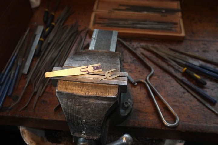
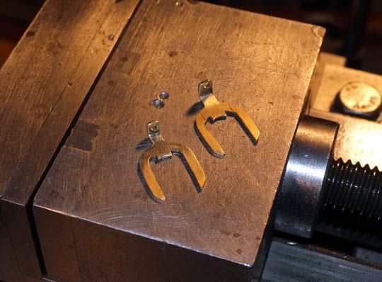
Last time, we were making the all-important hub. It was not quite finished, as the slots for the latch-and friction forks have yet to be put in. Also, I have been looking at pictures of Aerial hubs and have decided that my skills are not up to making the hub complete, as one piece. I'm going to make the little end cap, where the end-float adjusting screw goes, as a separate unit and solder the two together. This way I can get the spindle to perfectly match the hub, size-wise-and I have an idea for making a better end bearing..
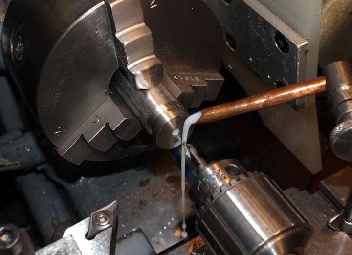
Making the spindle.
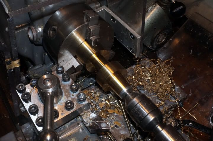
The material chosen was 17/4 ph stainless. This is an excellent metal for this task, free-cutting, non-corrosive and with good wear properties. I bought a small piece of 20mm diameter and started by roughing out all the excess material.
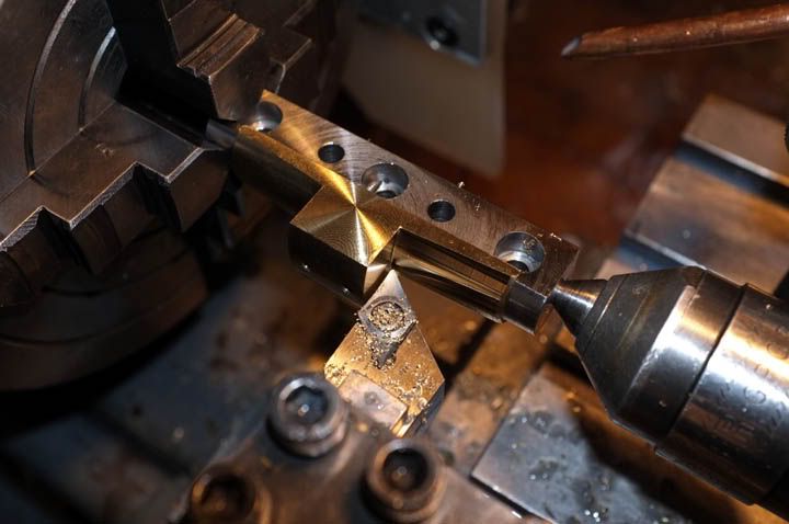
Here you see it being finish-turned to size..
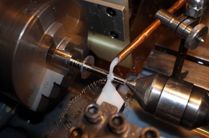
AS you see, I have already roughed out the end for locating into the star-back. I'm doing it like this so that all diameters are dead concentric.
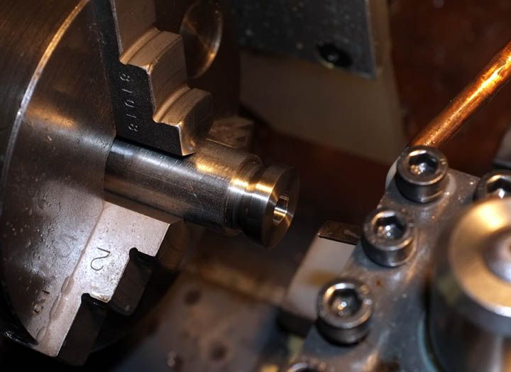
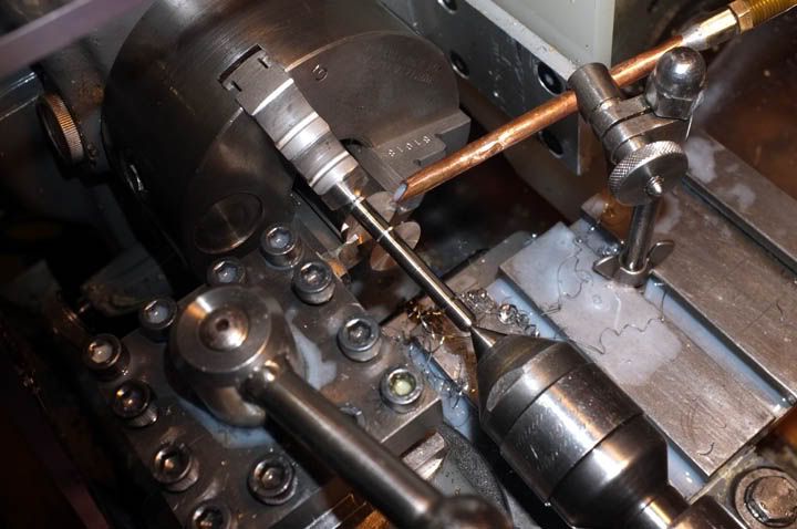
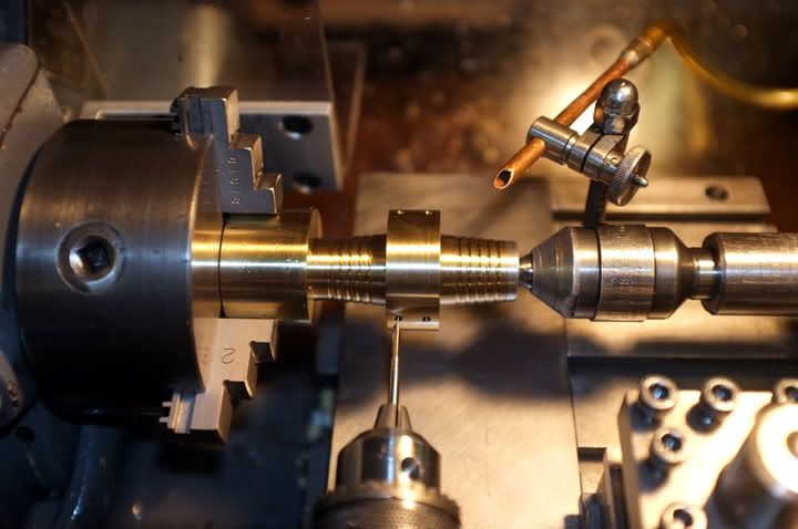
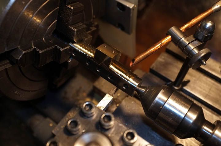
After the O/D is turned to size, I turned the little groove for the latch fork and a 0.010"relief in the centre. The hub will bear on the ends only to make for better free-running . Clearance between hub and spindle is 0.0005". This picture shows the star-back location being turned to size.
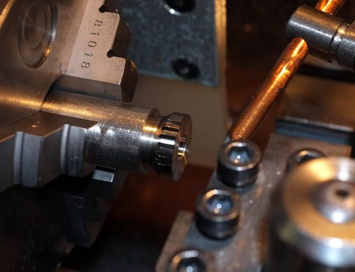
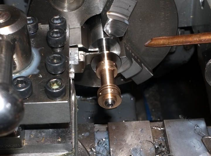
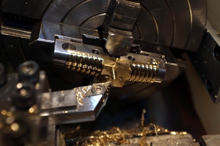
Here you see the hub being checked for fit. I have pressed in a small ball bearing into the end of the spindle on which the end-float adjuster screw will run. This will have a point contact to minimize friction.
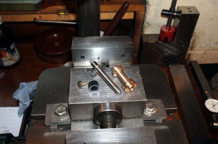
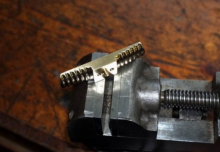
These are the spindle and hub components. The screw is for rear location and the little black delrin spacer will be pressed into the wooden back.
Getting saddled up!
I thought we could make the reel saddle now, which would more-or-less complete the star back.
I started by drilling out a piece of bronze with a 5/8" drill, then boring it out to produce the reel seat-or saddle- radius. I then roughly turned most of the excess metal away to produce this shape.
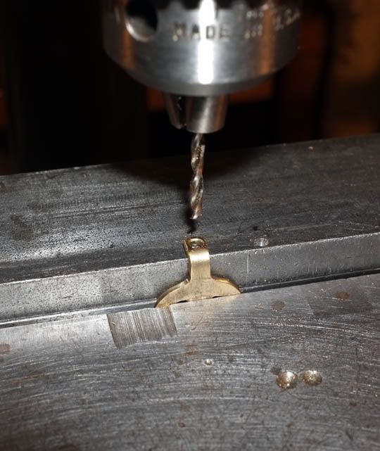
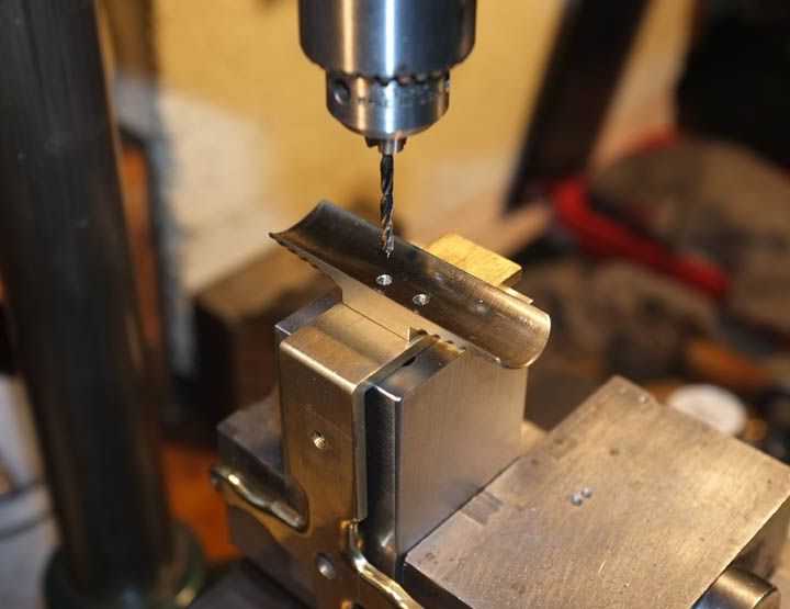
The drilling attachment was then set up and the M3 threads drilled and tapped in. I did this at 3 positions on the diameter as I can get 3 reel seats out of this.
It was then hacksawed into three more-or-less equal parts.
I made a simple arbor to screw one of the pieces on to, attached this to a small faceplate and faced of each side in turn to thickness.
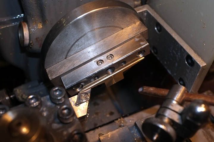
The arbor was then held in the 4-jaw chuck and the angles cut each end in turn.
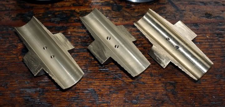
...and the grooves put in..
The arbor, complete with seat, was then held square in the 4-jaw and the base of the seat turned to produce a 1/8" location spigot in the centre.
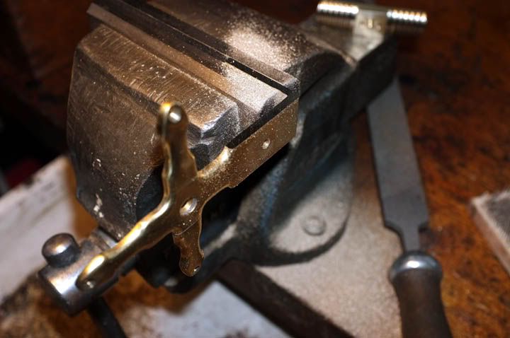
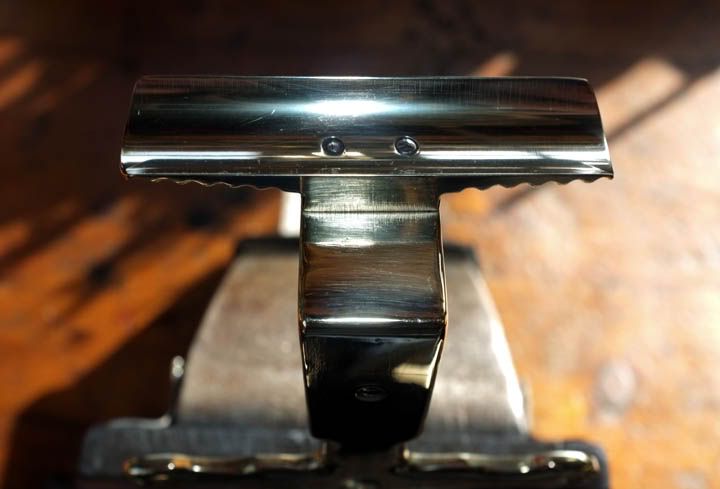
Now it was time to-literally-hand file and polish the seat to finish. Here we are, all done ready for fitting!
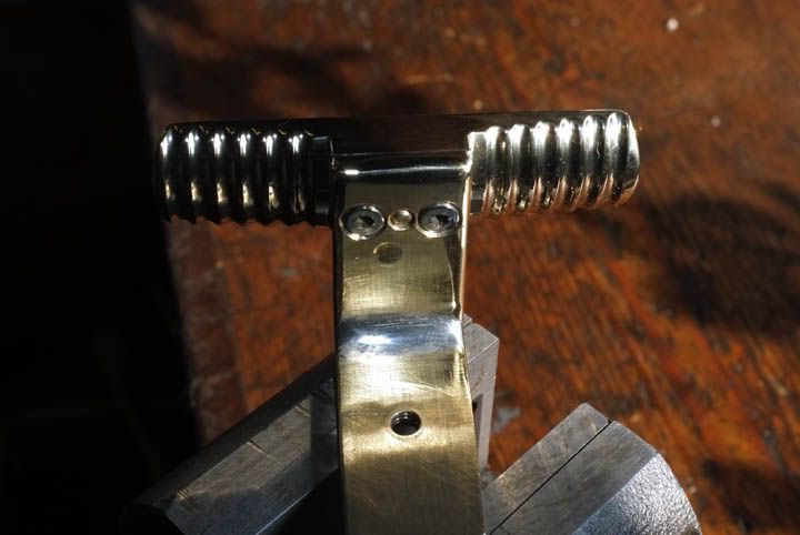
Turning attention to the star back, the seat was carefully positioned on the top and a 1/8" location hole drilled and reamed. the seat was located and then the holes were drilled for the fixing screws.
Now it was back to filing again. The surplus was cut from the top of the star back and the sides finished to blend in with the seat.
..and fitted together with countersunk M3 stainless screws from underneath.
Nearly done..
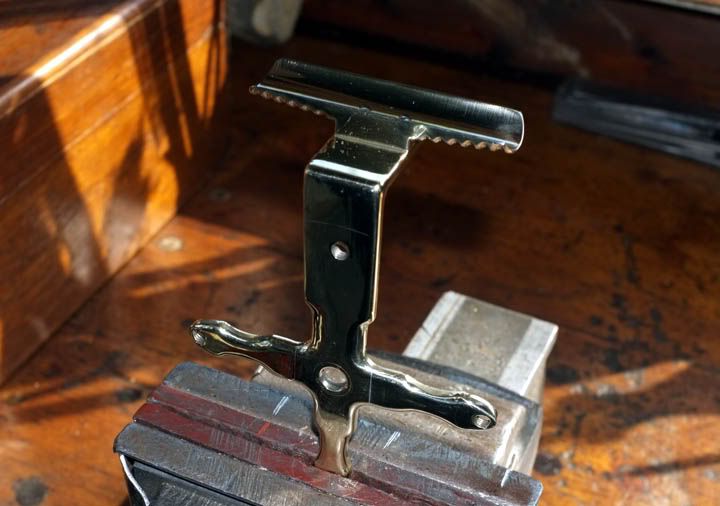
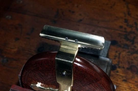
Polished to finish.
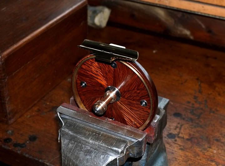
That's about as far as we can go for now with that. There will be one-or two holes to go in the back yet, to accept the optional check button-or lever, but here we are trying it for fit.
...and this is the story so far.. The hub is shown in position, but has not yet had the end cap fitted.
More next time..hopefully, I will have the spokes made by then...
Regards,
wm+